


Busduct Parts Explained: Every Part From the Transformer to the LT Panel
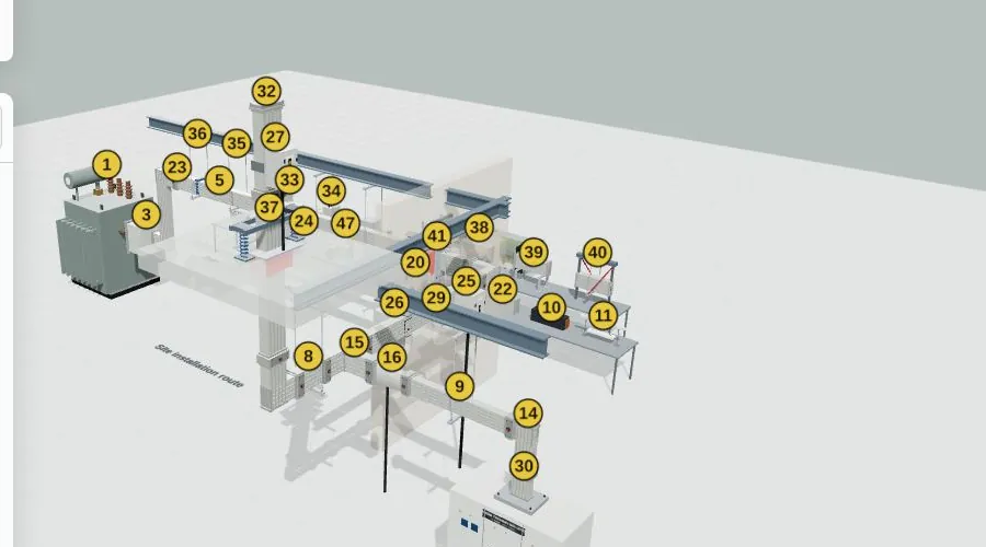
A busduct run looks like one long metal box, and on a drawing it is often shown as one line. On site it is forty or fifty separate parts, each with its own job, bolted together in a fixed order between the transformer and the LT panel. When a run fails in service, the failure is almost always at one of those parts: a joint that was never torqued, an expansion unit that was left out, a fire barrier that was fitted after the ceiling was closed.
This guide names every part of a low-voltage sandwich busduct run, group by group, in the order the current meets them. It says what each part does, where it sits, and the one thing a site engineer should check on it. It is written for a fresher, a diploma engineer or a buyer who has to read a busduct offer for the first time.
What a busduct is, and when it replaces cable
A busduct, or busbar trunking system, is a factory-made enclosure carrying rigid copper or aluminium conductors, supplied in standard lengths and fittings that bolt together on site to carry power from one point to another. The international product standard is IEC 61439-6, which is the busbar trunking part of the same family that governs the LT panel the run ends in.
Below a few hundred amperes, cable is cheaper and easier. Above roughly 800 A, the case for busduct gets stronger with every step in current: one 3200 A run replaces a bundle of parallel cables that needs its own trays, its own terminations at both ends, and its own derating calculation. Busduct also takes up less ceiling space, can be tapped at intervals along a plug-in length, and can be removed and re-used when a plant is re-laid out.
The trade-off is that busduct is a system. Every part has to be ordered to the drawing, and the route has to be surveyed before the order is placed. A cable run can absorb a surprise on site; a busduct run cannot.
Inside the housing: the sandwich construction
In a sandwich busduct, the phase and neutral bars are individually insulated and pressed tightly together inside the housing, with no air gap between them. The housing itself is usually aluminium or steel, and in most systems it doubles as the earth conductor, with an optional separate earth bar when the specification asks for one.
The sandwich has two consequences that matter at site. Because the bars are close and insulated, the reactance of the run is low, so the voltage drop over a long run is lower than the same current in cable. And because there is no air gap, heat from the bars is conducted straight to the housing and dissipated along the whole surface, which is why a sandwich run can carry its rated current without the ventilation an older air-insulated duct needed.
The parts described below are all built around this housing. A straight length is the housing with bars inside; a fitting is the housing bent or branched; a tap-off is an opening in the housing with a protected outlet.
Group 1: the source side
The run starts at the transformer, and the first three parts handle the mismatch between a transformer that vibrates and moves with temperature and a busduct that must stay fixed.
| Part | What it does | Check on site |
|---|---|---|
| Transformer connection unit, also called the throat | The adapter box that bolts to the transformer's LT terminal cover and gives the busduct its starting flange | Gasket and drain: the throat is the one part that is often outdoors or in a transformer bay |
| Flexible connector | Laminated copper or braided links between the transformer terminals and the first busduct bars, so transformer vibration does not reach the joints | Torque at both ends, and clearance from the tank wall |
| Phase transposition unit | Reorders the bars where the transformer's phase sequence does not match the busduct's | Phase sequence test before energising, not after |
Group 2: straight lengths
Straight lengths make up most of the run by metre. They are ordered to a drawing, in standard lengths of about three metres, with shorter cut lengths to make the route close.
- Feeder length. A plain straight length with no outlets. Carries power from A to B. The cheapest part per metre, and the one to use wherever no tap-off is needed.
- Plug-in length. A straight length with tap-off openings at fixed intervals along one or both sides, each closed by a cover until a tap-off box is fitted. Used along a shop floor or a riser where loads will be connected.
- Fire barrier length. A straight length with an internal fire barrier built into the housing at the point where the run crosses a wall or a floor slab. Rated as a complete assembly, not as a barrier stuffed in afterwards.
- Special or cut length. A length made to a non-standard dimension to make up the route. Every run has at least one. The drawing should show it, with its dimension, before the order goes.
- Lower-rating branch length. After a tee or a reducer, the branch continues at a lower rating in a smaller housing.
Group 3: fittings
Fittings change the direction or the rating of the run. They are the parts most often ordered wrong, because each one depends on which way the bars are stacked.
| Fitting | What it does |
|---|---|
| Edgewise elbow | Turns the run 90 degrees in the plane of the bars, so the housing turns on its narrow edge |
| Flatwise elbow | Turns the run 90 degrees across the plane of the bars, so the housing turns on its wide face |
| Edgewise offset (Z-unit) and flatwise offset | Two bends in one part, to step the run sideways or up and down around an obstruction |
| Tee | Splits the run into two directions, each at the rating of its branch |
| Cross | Splits the run into three directions |
| Reducer | Steps the run down to a lower rating, usually with a smaller housing section after it |
| Combination elbow | An edgewise and a flatwise bend in one part, for a corner that also changes level |
| Special angle elbow | A bend at an angle other than 90 degrees, made to the drawing |
| Expansion unit | A straight part with flexible links inside, which absorbs the thermal expansion of the bars along a long run |
The expansion unit is the fitting most often left out of an offer and most often missed on site. An aluminium bar run of forty metres grows by several millimetres between cold and full load, and without an expansion unit that growth goes into the joints and the supports.
Group 4: the joint
Every straight length and fitting meets the next one at a joint, and the joint is where a busduct run lives or dies.
- Joint pack. The assembly of insulating plates and conductive plates that clamps the ends of two adjacent sections together, phase to phase, with the housing bonded across the joint. Supplied as a single unit, usually fitted to one end of each section in the factory.
- Shear-head bolt with Belleville washer. The single bolt through the centre of the joint pack. Its head shears off at the design torque, so the joint cannot be under-torqued or over-torqued by hand, and the spring washer keeps the clamping force as the bars expand and contract.
The site check is a torque register: a sheet listing every joint on the run, with the date it was made, who made it and the confirmation that the head sheared. On a system that uses a plain bolt instead of a shear head, the register records the torque wrench setting. A run with no torque register has no proof that any joint is tight, and the first thermal scan after energising will usually find the one that is not.
Group 5: tap-off units
Along a plug-in length, each outlet can take a tap-off box, which is a small switchboard that plugs into the run and feeds one load or one distribution board.
| Tap-off type | Protection inside | Typical use |
|---|---|---|
| MCCB tap-off box | A moulded-case circuit breaker | A machine, a panel or a sub-distribution board on a shop floor |
| Fuse switch tap-off box | A switch-fuse unit | The same duty where the specification prefers fuses |
| MCB tap-off box | Miniature circuit breakers | Small loads on a riser in a building |
| Bolt-on tap-off | A fixed, bolted connection rather than a plug-in one | A large load that will never move |
| Blanking cover | No protection; closes an unused outlet | Every outlet that does not have a box on it |
A plug-in tap-off box normally has a mechanical interlock so that it cannot be plugged in or withdrawn with its breaker closed, and an earth contact that makes first and breaks last. Both should be checked on every box before the run is energised.
Group 6: termination
The run ends at a panel, a cable box or a cap.
- Panel flanged end. The adapter that bolts to the top or bottom of the LT panel and carries the bars through to the panel's incomer. It is made to the panel's cutout, so the panel drawing and the busduct drawing have to agree before either is built. This is where our work as an LT panel manufacturer in Vadodara meets the busduct supplier's work, and the flange is the usual place for the two drawings to disagree.
- Cable end feed box. A termination box with cable glands, used where the run is fed from or feeds into cable rather than a panel.
- Centre feed box. A feed box in the middle of a plug-in run, so that the run is fed from the centre and both halves carry half the current.
- End cap. Closes the open end of a run. Every run has at least one.
Group 7: supports
A busduct run weighs more than most people expect, and a sandwich run at high rating can be well over 50 kg a metre. The supports are a structural job, not an afterthought.
- Horizontal hanger. A bracket, usually on threaded rod from the slab, that carries the run at the spacing the manufacturer specifies. Spacing is typically between one and a half and three metres depending on the rating.
- Fixed point support. A hanger that clamps the housing so that it cannot slide. One fixed point per expansion unit, so the expansion goes into the unit and not into a joint.
- Vertical spring hanger. On a riser, a spring hanger that carries the weight of the vertical run and lets it move with temperature.
- Wall bracket and floor stand. Where the run goes along a wall or across a floor rather than from the ceiling.
- Seismic bracing. Diagonal bracing added where the building code calls for it.
Group 8: fire and building
Where the run passes through a wall or a floor, the opening has to be closed to the fire rating of the wall, and the run has to be sealed where it passes outdoors.
- Wall flange and floor flange. A plate around the housing that closes the opening and gives the fire-stopping material something to seal against.
- Internal fire barrier. The barrier inside a fire barrier length, which stops fire travelling along the inside of the housing.
- External fire stop. The fire-rated material packed around the housing in the opening, outside the duct.
- Wall entry seal. Where the run comes in from outdoors, a seal against water as well as fire.
The internal barrier and the external stop are two different things, and a run needs both. A fire barrier length with nothing packed around it is only half a barrier.
Group 9: protection and monitoring
- Joint temperature sensor. A sensor fitted at a joint and wired to a monitoring unit, so a joint that starts running hot is seen before it fails.
- Infrared inspection window. A window in the housing at a joint, so a thermal camera can see the bars without the run being opened.
- Danger and phase labels. Phase colours at every joint and tap-off, and the voltage warning along the run.
- Rain hood and IP kit. For a run outdoors, a canopy over the top of the housing and the gaskets and drains that bring the enclosure to its outdoor rating.
Group 10: the ground route
Not every run is at the ceiling. Where the transformer is outdoors and the LT panel is inside, the run often comes across the ground on floor stands, through the wall and into a trench to the panel's bottom entry. The ground route uses the same lengths, fittings and joints, plus a set of parts the ceiling route does not need:
- Outdoor transformer throat with hood, weatherproof, with a drain.
- Floor stands on RCC pedestals, hot-dip galvanised, anchored to the pedestal.
- Bollards or crash guards where a vehicle could reach the run.
- Walkway crossover where people have to cross it.
- Drain plug and breather at the low point of an outdoor run.
- Trench, trench supports and chequered-plate cover for the final approach to the panel.
- Panel bottom-entry flanged end, the mirror of the top-entry flange.
- Earthing links from the housing to the plant earth grid at the intervals the earthing design calls for.
How the parts go together on site: the fourteen steps
The sequence below is the order a busduct run is installed in, and the order the checks fall in.
- Drawing, site survey and route marking. Walk the route with the drawing and mark every hanger and every obstruction before anything is ordered.
- Material receipt. Check every part against the packing list, look for transport damage, and megger each length before it goes up, because a length that fails on the floor is cheaper than one that fails at the ceiling.
- Site storage. Dry, off the floor, ends capped.
- Hangers, floor stands and brackets. Level, at the specified spacing, with the fixed points in the positions the drawing shows.
- Lifting and placing the lengths. In sequence from the source end, with each length supported before the next is offered up.
- Joint assembly and the torque register. Each joint made, each shear head sheared, each one recorded.
- Elbows, tees, offsets and expansion units. Fitted as the run reaches them, never forced to make up a dimension error.
- Wall and slab crossings. Internal fire barrier length in the opening, external fire stop packed around it, flange fitted.
- Transformer throat and panel flanged end. The two terminations made last, after the run between them is fixed, so that neither end carries a stress.
- Tap-off boxes and interlock check. Each box plugged in, its interlock and earth-first contact checked.
- Earthing and bonding. Housing bonded across every joint, earth links to the grid, continuity measured.
- Pre-commissioning tests. Insulation resistance, continuity, phase sequence, and an audit of the torque register against the run.
- Energising and the first thermal scan. Under load, every joint scanned; the scan kept as the baseline for future maintenance.
- Handover documents. The as-built drawing, the torque register, the test results and the thermal scan, together.
The five mistakes that cost the most
- No torque register. The run is energised with no record of which joints were made and checked. The first hot joint is found by the thermal camera, or by the smell.
- No expansion unit on a long run. The bars grow with load, the growth goes into the joints and the hangers, and the joints loosen over the first summer.
- The fire barrier fitted late. The run goes through the wall as a plain feeder length because the fire barrier length was not on the order, and the opening is packed afterwards with material that is not rated for the duct.
- Panel flange and busduct flange built to different drawings. Found on the day the panel arrives, and fixed with an adapter plate that nobody designed.
- Tap-off outlets left open. A plug-in length with no blanking covers on its unused outlets is an open live enclosure.
Frequently Asked Questions
What are the main parts of a busduct system?
A busduct run is made of straight lengths (feeder and plug-in), fittings (elbows, offsets, tees, reducers and expansion units), joint packs between every section, tap-off boxes on the plug-in lengths, terminations at each end (transformer throat and panel flanged end, or cable feed boxes and end caps), the hangers and supports that carry it, the fire barriers and flanges where it crosses walls and floors, and the monitoring and labelling fitted along it.
What is the difference between a feeder length and a plug-in length?
A feeder length is a plain straight section with no outlets, used to carry power from one point to another. A plug-in length has tap-off openings at fixed intervals, each closed by a cover, so that tap-off boxes can be plugged in to feed loads along the run. Feeder lengths are cheaper and are used wherever no tap-off is needed.
What does a busduct joint pack do?
The joint pack clamps the bar ends of two adjacent sections together, phase to phase, through a stack of insulating and conductive plates, and bonds the housing across the joint. Most systems clamp it with a single shear-head bolt whose head shears off at the correct torque, so the joint cannot be under- or over-tightened. Every joint should be recorded in a torque register.
Why does a busduct run need an expansion unit?
The conductor bars expand as they heat up under load and contract as they cool. Over a long run that movement adds up to several millimetres, and without an expansion unit to absorb it the movement goes into the joints and the supports, which loosen over time. The rule is one expansion unit per the manufacturer's maximum straight run, with a fixed point support next to each one.
What is a tap-off box on a busduct?
A tap-off box is a small switchboard that plugs into an outlet on a plug-in length and feeds one load or one distribution board. It contains protection, usually an MCCB, a fuse switch or MCBs, and a mechanical interlock that stops it being plugged in or withdrawn with the breaker closed. Unused outlets are closed with blanking covers.
How is a busduct connected to the LT panel?
Through a panel flanged end, an adapter that bolts to the top or bottom of the panel and carries the bars through to the panel's incomer. The flange is made to the panel's cutout, so the busduct drawing and the panel drawing have to be checked against each other before either is built. It is the most common place for the two to disagree.
Related Guides
- LT panel busbar sizing calculation
- Electrical load list and transformer incomer sizing
- Panel earthing and earth busbar design
- Icu, Ics and Icw: short-circuit ratings of an LT panel
- IEC 61439 design verification vs routine verification
- Electrical panel FAT and routine test checklist
- Product page: PCC panels
- Product page: PMCC panel
- Free tool: Busbar size calculator
- Free tool: Transformer loading calculator
Talk to Us About Your Plant
Wisdom Techno Solutions manufactures the LT panel that a busduct run ends in: the PCC, the PMCC and the distribution boards, with the incomer and the flanged entry built to the busduct drawing, at our works in Vadodara, Gujarat. We build PCC panels and PMCC panels for industrial, EPC and infrastructure projects across India, and the same engineers who design an assembly test it before it ships.
Wisdom Techno Solutions is a licensed partner for three design-verified switchgear platforms: Rittal Ri4Power (Rittal Solutions Partner since 2021 — the Ri4Power system carries Intertek ASTA design verification to IEC 61439-1 and -2 Edition 3, with copper and aluminium busbar systems up to 6300 A), C&S CX (Licensed Partner since 2023, up to Form 4B Type II) and Siemens SIEPAN Elite/8PU (IEC 61439 Solutions Partner since 2024). We build to each system's verified configuration and routine-verify every assembly in-house at our Vadodara, Gujarat facility, for industrial, EPC and infrastructure projects across India.
If you are planning a transformer-to-panel run, send us the single line diagram and the busduct supplier's drawing. We will check the flange, the incomer rating and the panel cutout against it before anything is built.
Send your single line diagram or your load list, and we will come back with the panel scheme and the numbers behind it.